FRONT SUSPENSIONS
There are two major types of conventional front suspensions. They are dependent and independent.
Dependent Front Suspensions
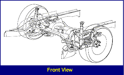
The dependent front suspension uses a solid axle. This design consists of one steel or aluminium beam extending the width of the vehicle. This beam is held in place by leaf springs.
Notice that this design also uses king pins and bushings to attach the wheels outboard of the axle. Because of its load carrying ability, the solid axle is only used on heavy trucks, and off-road vehicles. It is not suitable for use on modern passenger cars for three important reasons:
Transfer of Road Shock. There is transfer of road shock from one wheel to the other due to the way the wheels are connected to the axle. This causes a rough ride and could result in loss of traction.
Unsprung Weight. Because the solid axle has a lot of unsprung weight, it needs more spring and shock control to keep the tyres in contact with the road.
Wheel Alignment. The solid axle design makes no provisions for alignment.
Independent Front Suspensions
The independent front suspension was developed in the 1930’s to improve vehicle ride control and riding comfort. With the independent design, each wheel is mounted on its own axle. This allows the wheels to respond individually to road conditions. Also, with independent front suspension the sprung weight is reduced, creating a smoother ride.
Twin I-Beam
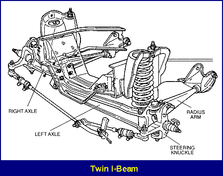
The twin I-beam is one type of independent front suspension. Although it is similar to the solid axle in many ways, it was designed to improve ride and handling. Because of its load carrying ability, it is used on pickups, vans and four-wheel drive vehicles.
The twin I-beam consists of two short I-beams supported by coil springs, and the steering knuckles, which are connected by, king pins or ball joints. The inner end of the axle connects to the vehicle frame through a rubber bushing. There is a radius arm connected to the frame through rubber bushings. This arm controls wheelbase and caster.
While the twin I-beam design was an improvement over the solid axle, it still has some flaws. For example, with the twin I-beam the camber and track change as the wheels move up and down creating tyre wear.
Type 1 Coil Spring
Now, let’s look at the coil spring suspension, another example of an independent front suspension. Notice that it is made up of the following components:
- two upper control arms
- two lower control arms
- two steering knuckles
- two spindles
- two upper ball joints
- two lower ball joints
- bushings
- coil springs
- shock absorbers
Notice that the control arms are of unequal length, with the upper arm shorter than the lower arm. This design is known as the short-arm/long-arm, or the parallel arm design.
Using control arms of unequal length causes a slight camber change as the vehicle travels through jounce and rebound. While this may sound bad, it actually is not. If both arms were the same length, a track change would occur causing the tyre to travel sideways. The tyres would then scrub the pavement, causing tyre wear and handling problems.
Notice that the shock and spring are positioned between the frame and the lower control arm. You can see that the bottom of the spring rests on the lower control arm, while the top of the spring is connected to the vehicle’s frame.
The outer end of the control arm is connected to the steering knuckle with ball joints. Ball joints are simple connectors, which consist of a ball and socket. The ball and socket assembly forms the steering axis for the suspension system.
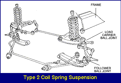
One ball joint is called the load carrier, meaning it carries the load of the vehicle or the force of the spring.
The other ball joint is called the follower. The follower does not carry any weight; it just provides a pivot point and stabilizes the steering system.
Typically, the location of the lower spring seat determines which ball joint is the load carrier and which is the follower.
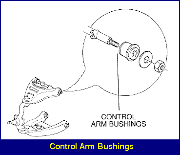
If the lower ball joint is the load carrier. The upper ball joint is then the follower. The control arms act as locators because they hold the position of the suspension in relation to the vehicle. They’re attached to the vehicle frame with rubber torsilastic bushings. Rubber bushings are preferred because they do not require lubrication, and will reduce minor road noise and vibrations. Torsilastic refers to the elastic nature of rubber to allow movement of the bushing in a twisting plane. Movement is allowed by twisting of the rubber.
The other sleeve of the bushing is press fit into the control arm, while the inner sleeve is locked to the control arm pivot shaft. The rubber must twist to allow movement of the control arm. This twisting action of the rubber will provide resistance to movement. Some sources state that “10% of the resistance to body roll comes from the rubber bushings.”
Control Arm Design
It is important to know that control arm design is matched with spring size. This produces an exact control arm position, allowing for travel over bumps. For this reason, the lower control arm must be horizontal or slightly lower at the ball joint end.
If you find that the ball joint end is higher than the inner control bushing, the springs may be weak and sagging. Weak or sagging springs may cause a track change, and can create tyre wear and handling problems. If you fi
Type 2 Coil Spring
Type 2 coil spring suspension, the coil spring is mounted on the upper control arm, and the top of the spring is attached to the frame.
In this type of design, the upper ball joint receives the weight of the vehicle and the force of the coil spring. This makes it the load carrier.
But the upper ball joint isn’t the only component supporting the vehicle weight. In the type 2 coil spring suspension, the coil spring also supports the weight of the vehicle. And the movement of the coil spring is controlled by the shock absorber.
Notice that in both Type 1 and Type 2 designs, the weight of the vehicle is transmitted through the spring to the control arm at its bottom, and then through the control to the ball joint.
You should know that the load carrying ball joints carry approximately one half of the total vehicle weight. This makes them subject to severe wear.
Stabilisers
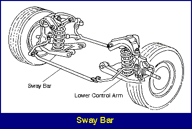
Another important component of the suspension system is the stabilizer. This device is used along with the shock absorbers to provide additional stability.
One example of a stabilizer is the sway bar, also known as the anti-sway bar.
The sway bar is simply a metal rod connected to both of the lower control arms. When the suspension at one wheel moves up and down, the sway bar transfers the movement to the other wheel. For example, if the right wheel drops into a dip, the sway bar transfers the movement to the opposite wheel. In this way, the sway bar creates a more level ride and reduces vehicle sway or lean during cornering.
Depending on the sway bar thickness and design, it can provide as much as 15% resistance to vehicle roll or sway during cornering.

Torsion Bar
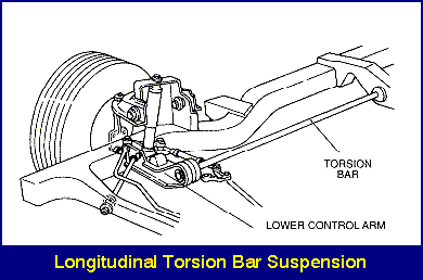
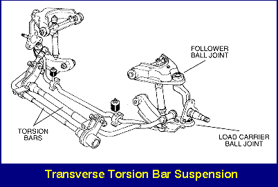
The torsion bar suspension is one more example of an independent front suspension. With the torsion bar suspension, there are no coil or leaf springs. Instead, a torsion bar supports the vehicle weight and absorbs the road shock.
Actually the torsion bar performs the same function as a coil spring: it supports the vehicle’s weight. The difference is that a coil spring compresses to allow the tyre and wheel to follow the road and absorb shock, while a torsion bar uses a twisting action. Other than this difference, however, the two types of suspension construction are much the same.
The torsion bar connects to the upper or lower control arm at one end, and at the other end connects to the frame. It can be mounted longitudinally, front to rear, or transversely, side to side. Unlike coil springs and leaf springs, torsion bars can be used to adjust suspension ride height.
Keep in mind, however, that torsion bars are not normally interchangeable from side to side. This is because the direction of the twisting or torsion is not the same on the left and right sides.
Because the torsion bar is connected to the lower control arm, the lower ball joint is the load carrier. This makes the upper ball joint the follower.
Notice that in this type of suspension the shock absorber is connected between the lower control arm and the vehicle frame. This allows it to control the twisting motion of the torsion bar.
Double Wishbone
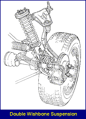
The double wishbone is another type of strut suspension that is becoming more common. It combines the space saving benefits of a strut suspension system with the ability of the parallel arm suspension to ride low to the ground. This allows for a more aerodynamic hoodline.
With this design, the lower portion of the strut forms a wishbone shape where it attaches to the lower control arm. Unlike other struts, the double wishbone does not rotate when the wheels turn. Instead, the entire spindle assembly rotates on the upper and lower ball joints much like a parallel arm suspension. Since the strut does not rotate, the upper mount does not need a bearing. Instead, a hard rubber bushing replaces the bearing and helps isolate road shock.
